
High-Precision Programmable Power Supply
The JPS-1500-6WF uses a “1+6” intelligent modular architecture (one monitor module plus six power modules) and can be expanded to six output channels, each independently controlled and replaceable without powering down. Local digital and remote analogue (4–20 mA) control are both supported, and a 24 V switch signal provides remote power cycling and mode switching. A radiation-tolerant model is available for space, nuclear and particle accelerator environments.
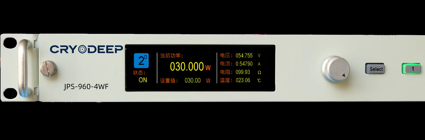
Three things modularity brings
Hot-swap, zero downtime
When any module needs service it can be replaced by hand from the front panel — no rear cabling to disconnect and no tools required — while the remaining channels keep running.
Four-wire temperature input
Standard four-wire PT100 / PT1000 inputs eliminate the error introduced by lead resistance, and are the precondition for ±0.1% class stability.
Remote sensing to cancel cable loss
The output stage provides remote sensing so that cable loss is compensated and the power delivered at the load matches the setpoint.
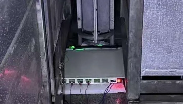
Holding its specified accuracy inside a radiation field
Designed for space, nuclear and particle accelerator environments. It withstands a cumulative dose of up to 100 Gy (cobalt-60) while powered, and continues to meet all specified parameters and functions afterwards. The image shows the unit powered up during testing in a radiation facility.

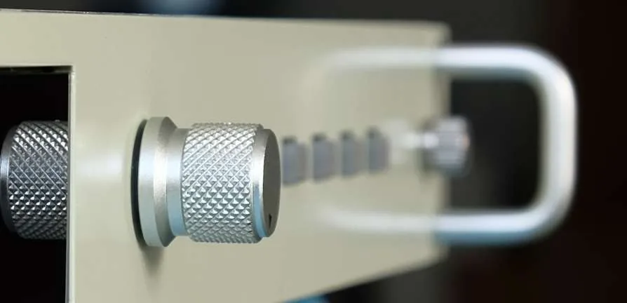
Five limit alarms, hardware interlocks, remote control
Five limit alarms — trip on violation
Output power, voltage, current, load resistance and heater temperature — each with independently settable upper and lower limits and a trip delay. On violation the affected power module shuts its output down and reports a fault code, so neither spurious nor missed trips occur.
Hardware interlocks that software cannot mask
Each channel has one interlock input and one interlock output (dry contacts). An open input is treated as a fault: every power module actively shuts down and reports a fault code. The protection is implemented in hardware and cannot be disabled in software under any circumstances.
24 V switch-signal remote control
A 24 V switch signal on the reset input cuts and restores the internal AC link from a distance for a remote power cycle; the mode input switches between local digital control and remote analogue (4–20 mA) control without anyone needing to change settings on site.
JPS-1500-6WF High-Precision Programmable Power Supply
The values below are nominal factory figures taken from the product brochure and the manual supplied with the unit; where the two differ, the supplied manual governs.
AC Input
AC INPUT| Input voltage range | Single-phase three-wire, 110 Vac – 265 Vac |
|---|---|
| Frequency range | 45 – 65 Hz |
| Input power factor per channel | ≥ 0.97 |
| Recommended upstream protection | Type C 16 A circuit breaker or fuse on the AC input |
Output Channels
OUTPUT| Output power | ≥ 1500 W |
|---|---|
| Number of output channels | 6 (each an independent power module) |
| Max output voltage per channel | ≥ 130 V |
| Max output current per channel | ≥ 1.95 A |
| Constant-power range per channel | at least 0 – 250 W |
| Load resistance range per channel | 10 Ω – 200 Ω |
| Control mode | Local digital and remote analogue control, switchable remotely or locally |
Accuracy & Stability
PRECISION| Constant-power error per channel | better than ≤ 0.1% rms (Ts ≥ 10 s) |
|---|---|
| 24-hour long-term stability | better than ≤ 0.1% rms |
| 24-hour power drift at room temperature | less than 0.1% |
| Setpoint resolution | 1 mW from host computer / 10 mW locally |
| Temperature input | Standard four-wire PT100 / PT1000 or thermocouple |
| Output compensation | Remote sensing (F+ / F−) to compensate output cable loss |
Environment & Interfaces
ENV / I-O| Operating temperature / humidity | -20 to 50 ℃; 10–80% RH, non-condensing |
|---|---|
| Storage temperature / humidity | -30 to 80 ℃; 10–90% RH, non-condensing |
| Dimensions | 480 (W) × 42.7 (H) × 474 (D) mm |
| Weight | 13.8 kg |
| Chassis | Less than 1U thick, suited to high-density 19-inch rack mounting |
| Network interface | 10/100BASE-TX auto-negotiating, TCP/IP server mode, web-based OTA update |
| Radiation tolerance | Meets all specified parameters after a cumulative absorbed dose of 100 Gy |
| EMC | Conducted emissions to EN55022A Class A |
Protection & Interlocks
PROTECTION| Hardware protection (cannot be disabled in software) | Input over/under-voltage, output over-voltage and over-current, power-device over-temperature, DC source over/under-voltage |
|---|---|
| Output-side protection | Over-current, over-voltage, over-temperature, open load, short circuit |
| Limit alarms (software enable / mask) | Output power, voltage, current, load resistance and heater temperature — each with upper/lower limits and a trip delay |
| Interlock input | One dry contact per channel, normally closed; on opening, all power modules actively shut down and report a fault code |
| Interlock output | One dry contact per channel; closed = healthy, open = fault |
| Fault display and reporting | Red status LED on the module key plus a fault code on screen — 14 codes in total |
| 24 V reset control | External 24 V switch signal: 24 V cuts the internal AC link, 0 V restores it — remote power cycle |
| 24 V mode control | External 24 V switch signal: 0 V selects local digital control, 24 V switches to remote analogue (4–20 mA) control |
HMI, Interfaces & Host Software
HMI / HOST| Front panel | LCD, shuttle knob, SELECT key and module keys 1–6 (red/green status LEDs; per-channel on, off and reset) |
|---|---|
| Rear panel | AC input switch and socket, Ethernet port, 24 V reset input, 24 V mode input, power module connectors 1–6 |
| Analogue interface | One input plus one output per channel, 4–20 mA spanning zero to full scale |
| Host software | Windows 10 / 11 (32/64-bit), .NET Framework 4.7.2 or later, no installation required |
| Live monitoring | Output power, voltage, current and load resistance per channel, with the last 5 minutes plotted |
| Data logging | Per-channel CSV logging, saved automatically into date-stamped folders |
| Parameter configuration | Batch or single-channel configuration of online channels; settings can be saved to a .conf file and reused |
| Firmware update | In-field APP and bootloader update over the network |
Need a radiation-tolerant model or a custom channel count?
Tell us the radiation dose, channel count and load parameters, and we will propose a dedicated configuration.